Troubleshooting Caller ID Problems
Several debugs can be used to troubleshoot the
Caller ID feature on the routers. The voice port module (VPM) signaling
debugs, such as the debug vpm signal
command, track the standard debugs with Caller ID feature turned on.
These debugs are analyzed from the perspective of the terminating router
and its FXO port; the caller ID is sent from this end. The following
example shows an FXO port receiving caller ID. In this example, the
phone sends the caller ID to the FXO port.
Nov 20 10:40:15.861 EST: [1/0/0] htsp_start_caller_id_rx
Nov 20 10:40:15.861 EST: [1/0/0] htsp_set_caller_id_rx:BELLCORE
Nov 20 10:40:15.861 EST: htsp_timer - 10000 msec
Nov 20 10:40:17.757 EST: [1/0/0, FXOLS_RINGING, E_DSP_SIG_0100]
Nov 20 10:40:17.757 EST: fxols_ringing_not
Nov 20 10:40:17.761 EST: htsp_timer_stop
Nov 20 10:40:17.761 EST: htsp_timer - 10000 msec
Nov 20 10:40:18.925 EST: [1/0/0] htsp_stop_caller_id_rx
Nov 20 10:40:21.857 EST: [1/0/0, FXOLS_RINGING, E_DSP_SIG_0000]
Nov 20 10:40:23.857 EST: [1/0/0, FXOLS_RINGING, E_DSP_SIG_0100]
Nov 20 10:40:23.857 EST: fxols_ringing_not
Nov 20 10:40:23.861 EST: htsp_timer_stop htsp_setup_ind
Nov 20 10:40:23.861 EST: [1/0/0] get_fxo_caller_id:Caller ID
received. Message type=128 length=31 checksum=74
Nov 20 10:40:23.861 EST: [1/0/0] Caller ID String 80 1C 01 08
31 31 32 30 31 35 34 30 02 07 35 35 35 31 32 31 32 07 07 4F 75
74 73 69 64 65 74
Nov 20 10:40:23.865 EST: [1/0/0] get_fxo_caller_id calling
num=5551212 calling name=Outside calling time=11/20 15:40
Nov 20 10:40:23.869 EST: [1/0/0, FXOLS_WAIT_SETUP_ACK,
E_HTSP_SETUP_ACK]
Nov 20 10:40:23.873 EST: fxols_wait_setup_ack:
Nov 20 10:40:23.873 EST: [1/0/0] set signal state = 0xC
timestamp = 0
Nov 20 10:40:23.985 EST: [1/0/0, FXOLS_PROCEEDING,
E_DSP_SIG_0100] fxols_proceed_clear
Nov 20 10:40:23.985 EST: htsp_timer_stop2
Nov 20 10:40:24.097 EST: [1/0/0, FXOLS_PROCEEDING,
E_DSP_SIG_0110] fxols_rvs_battery
Nov 20 10:40:24.097 EST: htsp_timer_stop2
Nov 20 10:40:24.733 EST: [1/0/0, FXOLS_PROCEED_RVS_BT,
E_HTSP_PROCEEDING] fxols_offhook_proc
Nov 20 10:40:24.733 EST: htsp_timer - 120000 msec
Nov 20 10:40:24.745 EST: [1/0/0, FXOLS_PROCEED_RVS_BT,
E_HTSP_VOICE_CUT_THROUGH] fxols_proc_voice
In this example, everything was working fine
and both Name and Number Display were properly delivered to the phone.
In the two scenarios below, the calling number is missing in one case,
and the name display is missing in the other.
Calling Number Lost, Name Delivered
In the following example, the calling number is lost, but the name is delivered:
Nov 17 17:39:34.164 EST: [1/1/0] htsp_set_caller_id_tx
calling num=display_info=Outside called num=9913050
Nov 17 17:39:34.164 EST: [1/1/0] Caller ID String 80 16
01 08 31 31 31 37 32 32 33 39 04 01 4F 07 07 4F 75 74
73 69 64 65 88
In the Caller ID String, looking at "04 01 4F" translates to:
04 : Reason for Absence of DN
01 : Length of message
4F : "Out of Area"
01 : Length of message
4F : "Out of Area"
Calling Number Delivered, Name Lost
In the following example, the calling number is delivered, but the name is lost:
Nov 17 17:53:24.034 EST: [1/1/0] htsp_set_caller_id_tx
calling num=5550109display_info= called num=5550011
Nov 17 17:53:24.034 EST: [1/1/0] Caller ID String 80
16 01 08 31 31 31 37 32 32 35 33 02 07 35 35 35 31 32
31 32 08 01 4F 05
In the Caller ID String, looking at "08 01 4F" translates to:
08 : Reason for Absence of Display
01 : Length
4F : Out of Area
01 : Length
4F : Out of Area
For more information, refer to Caller ID Name Delivery Issues on Cisco IOS Gateways, document ID 23444.
E&M Interfaces
The difference between a conventional two-wire
telephone interface such as FXS or FXO and an E&M interface is that
the E&M interface has wires that pass the audio signals plus wires
to act as an input (to sense an incoming call) or an output (to indicate
an outgoing call). These control leads are normally called the E lead
(input) and the M lead (output). Depending on the type of E&M
interface, the signaling leads could be controlled by connecting them to
the ground, switching a -48-Vdc source, or completing a current loop
between the two devices.
E&M interfaces can normally be two- or
four-wire operation, which does not refer to the total number of
physical connections on the port but rather to the way that audio is
passed between the devices. Two-wire operation means the transmitting
and receiving audio signals are passed through a single pair of wires
(one pair equals two wires). Four-wire operation uses one pair for
transmitting and another pair for receiving audio.
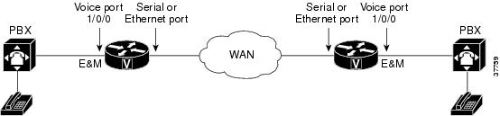
In Figure 18,
two PBXs are connected across a WAN by E&M interfaces. This
topology illustrates the path over a WAN between two geographically
separated offices in the same company.
Figure 18 E&M Signaling Interfaces
This section contains the following topics:
E&M Hardware Troubleshooting
The E&M interface typically connects remote
calls from an IP network to a PBX. Troubleshoot Cisco E&M hardware
by checking the following sections:
Software Compatibility
For interface cards inserted into Cisco modular access routers, check the compatibility tables in the "Overview of Cisco Interface Cards" chapter in the Cisco Interface Cards Installation Guide.
Cabling
E&M is a signaling technique for two-wire
and four-wire telephone and trunk interfaces. The E&M interface
typically connects remote calls from an IP network to a PBX. The card is
connected to the PSTN or PBX through a telephone wall outlet by a
straight-through RJ-48C cable.

Note  Refer to the appropriate platform product documentation for specific interface information about your E&M card.
The connector port for the E&M voice interface card is shown in Figure 19. Information about LEDs can be found in the "Connecting Voice Interface Cards to a Network" chapter of the Cisco Interface Cards Installation Guide.
Note Ports on the E&M voice interface card are color-coded brown.
Figure 19 Two-Port E&M Card Front Panel

To verify that the analog E&M hardware is being recognized by the Cisco IOS platform, use the following commands:
•show version—This
command displays the configuration of the system hardware, the software
version, the names of configuration files, and the boot images. See the
following sample output.
•show running-config—This
command shows the configuration of the Cisco platform. The voice ports
should appear in the configuration automatically. See the following
sample output.
show version Command on a Cisco 3640 Platform
Router# show version
Cisco Internetwork Operating System Software
IOS (tm) 3600 Software (C3640-IS-M), Version 12.1(2), RELEASE SOFTWARE (fc1)
Copyright (c) 1986-2000 by cisco Systems, Inc.
Compiled Wed 10-May-00 07:20 by linda
Image text-base: 0x600088F0, data-base: 0x60E38000
ROM: System Bootstrap, Version 11.1(20)AA2, EARLY DEPLOYMENT RELEASE SOFTWARE(fc1)
Router uptime is 0 minutes
System returned to ROM by power-on at 11:16:21 cst Mon Mar 12 2001
System image file is "flash:c3640-is-mz.121-2.bin"
cisco 3640 (R4700) processor (revision 0x00) with 126976K/4096K bytes of memory.
Processor board ID 16187704
R4700 CPU at 100Mhz, Implementation 33, Rev 1.0
Bridging software.
X.25 software, Version 3.0.0.
SuperLAT software (copyright 1990 by Meridian Technology Corp).
2 Ethernet/IEEE 802.3 interface(s)
2 Voice FXS interface(s)
2 Voice E&M interface(s)
DRAM configuration is 64 bits wide with parity disabled.
125K bytes of non-volatile configuration memory.
32768K bytes of processor board System flash (Read/Write)
20480K bytes of processor board PCMCIA Slot0 flash (Read/Write)
Configuration register is 0x2102
show running-config Command on a Cisco 3640 Platform
Router# show running-config
Building configuration...
Current configuration:
!
!--- Some output omitted.
version 12.1
service timestamps debug uptime
service timestamps log uptime
!
hostname Router
!
voice-port 3/0/0
!
voice-port 3/0/1
!
voice-port 3/1/0
!
voice-port 3/1/1
!
end
Shutdown Port
Check to make sure the port is not shut down. Enter the show voice port command with the voice port number that you are troubleshooting. The output will tell you:
•If the voice port is up. If it is not, use the no shutdown command to make it active.
•What
parameter values have been set for the voice port, including default
values (default values do not appear in the output from the show running-config command). If these values do not match those of the telephony connection you are making, reconfigure the voice port.
E&M Interface Types
This section describes the standard analog
E&M interface types I, II, III, and V (IV is not supported by Cisco
platforms). The following topics are covered:
E&M Signaling Unit Side and Trunk Circuit Side Compatibility Issues
E&M signaling defines a trunk circuit side
and a signaling unit side for each connection. Cisco's analog E&M
interface functions as the signaling unit side, so it expects the other
side to be a trunk circuit. When you use E&M interface model Type II
or Type V, you can connect two signaling unit sides back to back by
appropriate crossing of the signaling leads. When using the E&M Type
I or Type III interface, you cannot connect two signaling unit sides
back to back.
Many PBX brands have E&M analog trunk cards
that can operate as either the trunk circuit side or the signaling unit
side. Because the Cisco E&M interfaces are fixed as the signaling
unit side of the interface, it may be necessary to change the E&M
trunk settings on the PBX to operate as the trunk circuit side. If Type I
or III E&M is being used, this is the only way the PBX can work
with the Cisco E&M interface.
Some PBX products (and many key systems) can
operate only as the signaling unit side of the E&M interface. They
cannot interoperate with the Cisco E&M interface if Type I or Type
III is chosen. If Type II or Type V E&M is being used, PBX products
fixed as "signaling unit" side can still be used with the Cisco E&M
interface via Type II or Type V.
Each E&M signaling type has a unique
circuit model and connection diagram. The following sections describe
the different types. Table 25 shows the E&M supervisory signal description.


No comments:
Post a Comment